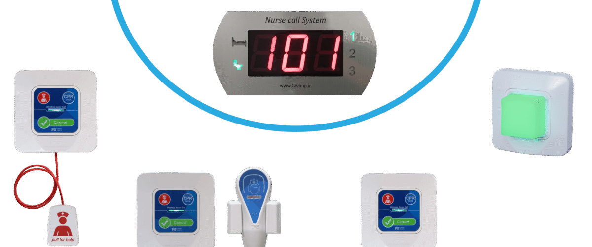
Nurse Call System Implementation Standard According to Publication No. 89 of the National Building Regulations – Hospital Electrical Installations
Signaling and nurse call systems
Signaling and nurse call systems, which use visual and audible signals to establish communication between patients and hospital staff, are used according to their application as follows:
1- Wireless nurse call system of the simple visual and audible type
Such systems, which may be used for clinics and small hospitals, include the following equipment and operating mode:

1-1 The equipment used in this type of systems includes the following: Click here to view the implementation specifications of this system
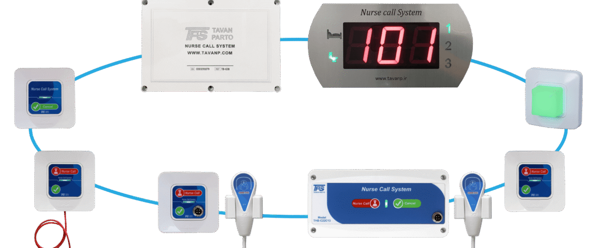
– Numerafor (call annunciator) for installation at the nurses’ station of each ward, of the flush-mounted or surface-mounted wall type, with signal lamps and buzzer, but without a call-cancel system.
– Safety-type power transformer with separate primary and secondary windings, with power, voltage and frequency appropriate to the application.
– Bedside call plug of the flush-mounted type, without relay, equipped with a dedicated connector for the pear-shaped handset (under-pillow handset) and with a dedicated cable for the patient bed.
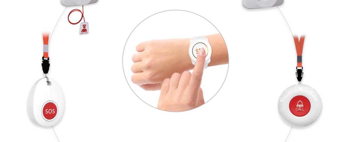
– Call plug for the private toilets of patient rooms and the public toilets of each ward, of the flush-mounted pull-cord type with pull hook and related chain, and without relay.
– Answer (cancel) plate for installation beside the entrance door inside each room, of the flush-mounted type, including a signal lamp.
– Over-door lamp for installation above or beside the door of each room in the corridor.
2-1 The operating mode is as follows:
Call: if any of the push buttons of the call plugs is pressed, the signal lamp on the answer plate inside the room, the over-door lamp, and the signal lamp on the numerafor device – on which the room numbers are indicated – must light up, and the buzzer of the numerafor device must also sound.
2- Nurse call system of the simple visual and audible type (communication via network cable)
Such systems, which may be used for large hospitals, include the following equipment and operating mode:

1-2 The equipment used in this type of systems includes the following: Click here to view the implementation specifications of this system
– Numerafor (call annunciator) for installation at the nurses’ station of each ward, of the flush-mounted or surface-mounted wall type, with signal lamps and buzzer, but without a call-cancel system.
– Safety-type power transformer with separate primary and secondary windings, with power, voltage and frequency appropriate to the application.
– Bedside call plug of the flush-mounted type, equipped with a dedicated connector for the pear-shaped handset (under-pillow handset) and with a dedicated cable for the patient bed.
– Call plug for the private toilets of patient rooms and the public toilets of each ward, of the flush-mounted pull-cord type with pull hook and related chain.
– Answer (cancel) plate for installation beside the entrance door inside each room, of the flush-mounted type, including a signal lamp.
– Over-door lamp for installation above or beside the door of each room in the corridor.
– Terminal box for terminating the equipment cables and connecting to the central display.
2-2 The operating mode is as follows:
Call: if any of the push buttons of the call plugs is pressed, the signal lamp on the answer plate inside the room, the over-door lamp, and the signal lamp on the numerafor device – on which the room numbers are indicated – must light up, and the buzzer of the numerafor device must also sound.
3- Visual-audible nurse call system with conversation capability
Such systems, which may be used for large hospitals, include the following equipment and operating mode:
1-3 Appliances and equipment

The appliances and equipment used in this type of systems include the following: Click here to view the implementation specifications of this system
Central nurse call device: such devices may be of the surface-mounted or desktop types with the required number of circuits, proportionate to the number of rooms, plus 4 to 6 spare circuits, for installation on the counter of the nurses’ station of each ward; and include the power supply device, the power on/off switch with a lamp indicating whether the device is on or off, an audio amplifier with input and output volume control, paging button, loudspeaker, microphone, telephone handset and mouthpiece for confidential conversation, electronic buzzer-tone, signal lamp or optical indicator, selector push buttons proportionate to the number of device circuits, cancel push button, and all related accessories.
Subsidiary nurse call device: the subsidiary nurse call device must be of the flush-mounted type with a polished anti-rust plate, installable on the wall of the nurses’ work room of each ward, and include a loudspeaker, microphone, signal lamp and cancel switch. Bedside call plug: such plugs must be of the flush-mounted type with a polished anti-rust metal plate, installable on the wall or shelf beside the bed. Bedside call plugs include a command relay, call-cancel push button, signal lamp, dedicated connector for installing the pear-shaped handset with cable, omnidirectional microphone, loudspeaker, and confidential-conversation switch; and their design must be such that the patient can easily contact the nurses’ station without getting out of bed or making extra movements and without raising his voice.
Toilet call plug: the toilet call plug must be of the pull-cord type, flush-mounted, without relay and signal lamp, with a polished anti-rust metal plate, installable on the wall inside the private toilets of patient rooms or the public toilets of each ward.
Toilet answer plate: the toilet answer plate must be of the flush-mounted type with a polished anti-rust metal plate, installable on the wall beside the entrance door inside the room or public toilet, and include a command relay, signal lamp and call-cancel push button.
Over-door lamps and corridor intersections: over-door lamps and corridor-intersection lamps must be of the surface-mounted or semi-flush type, with a protruding globe visible from every side, installable above or beside the entrance door of each room in the corridor or at corridor intersections, and include two lamps – one white for signaling with the bedside plug, and the other red for signaling with the toilet call plug.
2-3 Operating mode
The operating mode is as follows:
a- Call by means of the call plug located beside the patient’s bed
If any of the push buttons of the call plugs installed beside the patients’ beds is pressed in any of the rooms, the signal lamp of the call plug, the white lamp of the over-door light, the corridor-intersection light, the signal lamp of the related room located on the central nurse call device, and the signal lamp of the subsidiary nurse call device must light up, and the electronic buzzer-tone of the central device and of the subsidiary nurse call device must also sound.
Answer: if the selector push button related to the calling room, located on the central nurse call device, is pressed, then – in order to avoid communication with two rooms at the same time – all previous connections must be disconnected automatically, all the above-described signal lamps must go out, the sound of the buzzers or electronic tones must stop, and the necessary connection for two-way conversation between the nurse and the calling patient must be established.
b- Call by means of the toilet call plug
If the pull push button or the pressure push button of the call plug in any of the toilets is pulled or pressed, the signal lamp on the answer plate inside the room, the red signal lamp of the over-door and corridor-intersection lights, and the red signal lamp on the central device and the subsidiary nurse call device must light up, and the buzzer or electronic tone of the devices must also sound.
Call cancellation: cancellation of the call must only be possible from inside the calling room or toilet, after attending the related location, by pressing the cancel push button of the answer plate.
4-Visual nurse call system– audible, microprocessor-based, with main centers
The two-way conversation capability of such systems includes, as applicable, the following equipment and facilities:
1-4 Appliances and equipmentClick here to view the implementation specifications of this system
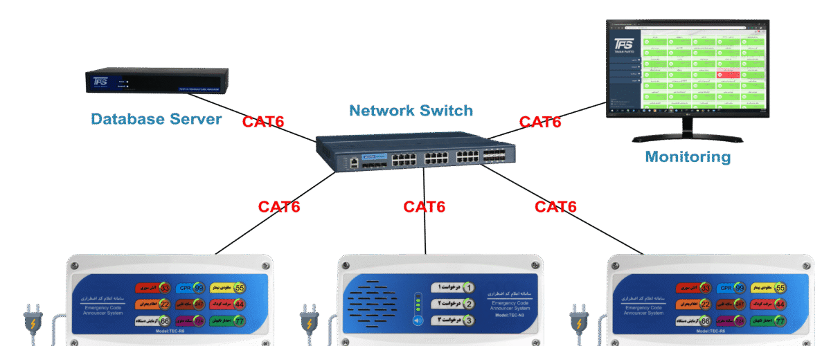
a- Central processing unit (CPU): the central processing unit may be selected with addressable capacities of 64, 128, 256 or 512 points proportionate to the capacity and size of the hospital in question, with the capability of connecting to the required number of primary and secondary main centers, together with monitor, necessary keys and related handset.
The said device may be selected as a dual network or of the single type. The said set may also be equipped with printers and pocket paging devices.
b- Accessories and peripheral equipment: the accessories include the following:
Bedside call and communication plug: this type of plug must be equipped with the required number of pins, may be selected of the single or double types, and includes, as applicable, a microphone, loudspeaker and related connection cable.
Bathroom and toilet call plug: these plugs, which may be of the pull-cord or pyramidal types, may be selected – according to the environmental conditions – of the type suitable for dry or wet environments.
Over-door lamps and corridor intersections: over-door lamps and corridor-intersection lamps must be of the surface-mounted or semi-flush type with a protruding globe visible from every side, installable above or beside the entrance door of each room in the corridor or at corridor intersections.
Uninterruptible power supply (UPS): in order to support and continue the power supply of each of the call systems, an uninterruptible power system proportionate to the needs of each system and in accordance with the criteria and technical specifications provided in Chapter 8 of Publication 110-2 must be foreseen and provided.
2-4 Fault-finding system with loop wiring
To ensure the correct operation of each of the parts, the call system must be equipped with a fault-finding system with loop wiring.
3-4 Operating mode
In all main centers, wards or rooms in question, the selection system and the priority level of patients and room conditions may be determined or changed there. Paging zones may also be determined or, if necessary, changed. In the main centers, using an alphanumeric system, zones and rooms may be programmed and linked to the related center. The programming of each main center, or part of a menu, may be protected against possible or unauthorized changes by a password.
5- Technical construction specifications and equipment of signaling and nurse call systems
The equipment of signaling and nurse call systems must be designed, manufactured and tested in accordance with one of the valid and recognized international standards such as IEC, BS, VDE or UL. The most important technical construction specifications of the said systems, based on the UL1069 standard, are as follows:
1-5- Definitions
a- Centralized system: a system equipped with an operator console and related subsidiary stations with a trained operator, usually installed in a location from which the patient rooms are not visible from its control center.
b- Conventional system: a system comprising one or more nursing stations (usually for one floor or one wing of the building) in which nursing staff are present, installed in a location from which each of its related rooms is visible or easily accessible.
c- Attendance center: a center or station at which hospital staff (nurses, nursing aides, service personnel and the like) are to register their presence.
d- Low-voltage circuit (power-limited): a circuit whose effective voltage does not exceed 30 volts (peak voltage 42.4 volts, direct or alternating) and whose nominal output power does not exceed 100 volt-amperes.
e- High-voltage circuit: a circuit whose voltage and power specifications exceed those defined in clause “d” for a power-limited low-voltage circuit.
f- Coded call signal: an audible and visual signal indicating a condition that threatens human life and makes immediate action necessary.
g- Emergency signal: an audible and visual message that requires immediate action but is not necessarily an indication of a life threat.
h- Grounded conductor: a system or circuit conductor that has been intentionally grounded.
i- Grounding electrode conductor: a conductor used to connect the grounded equipment or circuit of a wiring system to the grounding electrode or electrodes.
j- Equipment grounding conductor: the conductor used to connect the non-current-carrying metal parts of equipment, raceways and other enclosures to the grounded system conductor, to the grounding electrode conductor, or to both, at the service equipment location or at the source of a separately derived system.
k- Leakage current: any current, including capacitively coupled currents, that may be transferred from the accessible parts of a product to ground or to other parts of it.
l- Patient care areas : The various patient care areas, according to the type of foreseen services, are as follows:
– General care areas: such areas include patient rooms, examination and treatment rooms, clinics, and similar areas in which the patient comes into contact with ordinary devices such as the nurse call system, electric beds, examination lamps, telephone, and entertainment devices (television). In this type of areas the patient may also come into contact with electric medical devices such as electric mattresses, electrocardiography, suction pumps, monitors, ear and eye examination equipment, and other intravenous accessories.
– Special care areas: This type of areas includes cardiac care units (CCU), intensive care units (ICU), angiography and sonography units, operating and delivery rooms, and similar areas in which patients receive special care and are treated using electric medical devices.
– Wet areas: working environments that usually have wet conditions – such as locations with standing water on the floor or that are normally exposed to wetness and dripping – are counted as wet areas. Ordinary measures for cleaning the environment or accidental spilling of liquids do not make an area a wet area.
2-5- Enclosure or box
The enclosure of nurse call equipment must be shaped and mounted in a way that provides sufficient strength and durability against the shocks and probable damages of the operating period, and all its electrical parts must be covered in a way that minimizes the possibility of contact with uninsulated live parts. (For the minimum thickness and material of device enclosures, refer to Chapter 3 of Publication 110-2)
3-5- Protection against electric shock
a- The parts of devices and equipment that are accessible to the operator during repair and maintenance must not present an electric-shock hazard.
b- The terminals foreseen for connecting an external antenna must be connected to the grounded conductor of the supply circuit.
c- Where interconnectable components are used, inserting a plug into a socket must not cause electric shock.
4-5- Protection against rust and corrosion
Iron and steel parts, except bearings and the like for which this type of protection is not applicable, must be protected against rust and corrosion by enameling, galvanizing, plating and the like.
5-5- Equipment grounding
a- The equipment of the nurse call system and hospital signaling systems must be equipped with a separate terminal or wire for grounding. The said terminal or wire must be connected to all accessible non-current-carrying metal parts that may become live, as well as to all internal non-current-carrying metal parts of the devices that are accessible during operation or repair.
b- The colored insulated conductors used for equipment grounding must be of the dual green/yellow color, and no other conductor may be identified by this color. The cross-section of such conductors must be at least equal to the cross-section of the supply conductors. c- The screw used for the equipment grounding terminal must be of the hexagonal or slotted type, or with both features, and its head must be green. Such screws must be located where, during repair and maintenance of the device, their disconnection and removal is not probable.
6-5- Components of signaling and nurse call systems: the appliances and equipment used in nurse call and signaling systems, including the following, must comply with the specifications and criteria stated in Chapter 3 of Publication 110-2:
a- Printed circuit boards b- Windings c- Switches d- Lamps and lampholders
e- Protection and control equipment f- Sockets and connectors g- Transformers
h- Current-carrying parts i- Insulation j- Operating mechanisms
k- Second (emergency) power source l- Clearances between different parts
7-5- Electrical supervision system
Conventional or centralized nurse call systems must be equipped with an electrical supervision system in the following cases, and must audibly announce the existence of a fault in the circuits and system components, identifying the circuit in question, at the nursing station or control center:
a- A single open circuit, or a single ground circuit, or a short circuit of two or more conductors connected to coded nurse call stations
b- A single open conductor, or single ground, or short circuit of two or more conductors between control units interconnected in a centralized system. Exception: for non-coded nurse call systems, if in each nursing zone a stationed station or its equivalent, with visual and audible indicators, controls and announces the calls of a zone, a building wing or a floor, the use of an electrical supervision system will not be necessary.
c- All single open conductors, single grounds, and conductors connected to the hearing appliances and loudspeakers used for emergency conditions in the coded call system. Every fault-indicating signal must be different from all nurse call signals and distinguishable, and must sound an audible device, which may be shared by several circuits. A silence switch must only be provided if a visual indication remains. The visual indication must remain until the silence switch is returned to its initial position. After the fault is cleared, if the switch is in the silence position, the audible system must sound. Where the audible system sounds again if the fault persists, the visual indicator will not be required.
8-5- Testing
Signal-generating and nurse call systems must be tested against one of the recognized and valid similar world standards, in accordance with the criteria provided in the related clause of the UL1069 standard, as follows: a- Test of measuring the voltage and current of input and output circuits, as well as measuring the volt-ampere capacity of the circuits (per clause 20)
b- Test of operation under overvoltage conditions (per clause 21) – high-voltage power supplies and signal units must resist, without damage, the continuous application of 110 percent of the nominal input voltage, and the system of units connected to the output of the power supplies must be able to perform the signaling function despite the excess voltage. – Units connected to the output of high-voltage power supplies or high-voltage signaling units must be able to perform the intended function at 85 percent of the nominal voltage.
c- Test of stability against impact or vibration (per clause 22) d- Thermal stability test (per clause 23)
(e- Overload test (per clause 24) f- Endurance test (per clause 25)
g- Test of ambient temperature changes (per clause 26) h- Humidity test (per clause 27)
i- Electric shock test (per clause 28) j- Leakage current test (per clause 29)
k- Transient test ((per clause 30) l- Dielectric voltage stability test (per clause 31)
m- Drop test of appliances (per clause 32) n- Component failure test (per clause 33)
o- Tests of operation under abnormal conditions (per clause 34) p- Tests of special terminal assemblies (per clause 35)
q- Test of strain-relief appliances and supply cables (per clause 37)
r- Water-splash test for installing appliances in wet locations (per clause 38)
s- Impact test for non-metallic enclosures (per clause 39)
t- Dielectric test on the production line (per clause 40)
u- Ground-connection continuity test on the production line (per clause 41)
9-5- Marking
The following information must be marked clearly and permanently on each signal-generating device, in a location easily visible after installation. The said information must be written either directly on the device or on a separate installation drawing specified in the marking.
a- Name of the device manufacturer or its identifying logo (marked on the device)
b- Model number and date code or equivalent (marked on the device)
c- Nominal electrical ratings (marked on the device)
d- Correct installation position (if the device must be installed in a specific position)
e- Identification of lamps, switches, measuring instruments and the like in terms of device function
f- Maximum nominal fuse rating on each fuse holder g- Reference to the installation wiring drawing, if not affixed to the device, stating its number and issue date (marked on the main terminal of the box or power supply)
h- Pendant controls used in oxygen-enriched environments must be suitable for the environment in question; otherwise they must be marked in accordance with the criteria stated in the UL1605 standard.
i- Switches used for emergency cases must be marked by inscribing the word “Emergency” and the like in a distinct color (preferably red), in a visible location and permanently. The uses of other switches must also be identified.
j- Where cable assemblies contain high-voltage and low-voltage wires, the high-voltage wires must be marked and identified.
6-Signal systems and equipment with programmatic control
Stored-program signal-generating systems and equipment must meet the following conditions:
a- The operating program must be changeable by the user, and its instructions must be provided in a separate manual and its application approved. This program may include the introduction of input points and devices, the determination of station priorities and the like. The operating program may also include additional input and output information such as patient file data.
b- As part of the programmatic control system, where the central (main) microprocessor in the control unit, or the central station, encounters a fault in executing the intended program, an audible signal must be activated within 90 seconds and announce the existence of the fault.
c- Signal and nurse call systems must be designed so that the operation of the system is not disrupted if the subprograms are not executed.
d- Where the program information is stored in volatile memory, the system must be equipped with facilities that allow the program to be restarted and the complete stored program (operating and user programs) to be placed in the memory again. The system must also have facilities to create a permanent copy of all the user data entered into it.
e- Volatile memory is a memory whose information is lost upon power interruption.
f- Compliance with the conditions stated in clause “d” must not rely on devices whose storage-memory interface is subject to continuous wear during normal operation and is not protected against atmospheric contamination.
7- Principles and methods of installing signal-generating and nurse call systems
1-7- Installation and operation drawings and instructions
1–1–7–Every signal-generating and nurse call system must have an installation and operation manual containing the following information:
a- Instructions of the installation drawings of each device. Where devices must be installed in a special position, this must be specified in the installation instructions or by marking on the device.
b- The location of the controls on the devices must be shown graphically.
c- Description of the function of each of the control switches
d- Step-by-step method of using the devices
e- Periodic recommendations for servicing and maintaining the devices
f- Safety considerations for using and servicing the devices g- Circuit diagrams h- Description of circuit operation
2-1-7-Every nurse call system or signal unit must, as applicable, have one or more installation wiring drawings. The said drawing or drawings must be affixed to the main control device; if provided separately, the drawing number and its issue date must be marked on the main control and reference made to the related drawing or drawings.
3-1-7- The installation wiring drawing must have a pictorial view or its equivalent of the locations of the wire and cable connections and the related terminals. The terminal numbers on the device and on the drawing must be identical.
4-1-7-The connection drawing of the installation wiring circuits of the devices must contain the following information:
a- Main device supply circuit: this circuit must contain information about the voltage level, frequency, and maximum input current or consumption (watts), and a terminal or wire for connecting the protective grounding conductor must be specified.
b- Circuits of devices connectable to the patient: in the wiring drawing of such circuits the maximum number of connectable units and the maximum load that may be connected to the circuit in question must be specified and shown.
c- Pendant control circuits: circuits not specifically foreseen for nurse call and signal systems must be marked in a way that either the type of device connected to them is identified by stating the device type and its serial number, or their electrical characteristics – including voltage and amperage or consumed watts and frequency – are stated.
5-1-7-Where special tools are used to connect to the terminals of power-limited low-voltage circuits, the type of tool used must be stated in the installation instructions.
6-1-7-Where systems or devices are controlled by a program, a separate section must be foreseen in the system installation instructions – or a separate manual must be provided – for making the authorized changes in the system for normal operation.
2-7- Conduit and wiring system
1-2-7-The wiring or cabling of signaling and nurse call systems must be executed inside rigid steel or plastic conduits, separately, according to the executive drawing of the manufacturer of the said systems, as follows:
a- Where the wiring system is executed inside the building, the insulation and sheath of the cable must be of the plastic type and, for audio system circuits, must have a guard (shield).
b- Where the wiring system is executed outside the building, the insulation and sheath of the cable must be of the polyethylene or polyolefin type and, for audio system circuits, must also have a guard (shield).
2-2-7-The technical specifications of the conduits used in the conduit system of nurse call and signaling systems, as well as their executive criteria, must comply with the criteria provided in Chapter 1 of Publication 110-1 (first revision). Likewise, the technical specifications of the wires and cables used and their executive criteria must, as applicable, comply with the criteria provided in Chapter 1 of Publication 110-2 and Chapter 2 of Publication 110-1 (first revision).
3-2-7-The connections of the metal conduit system, including under-panel and distribution boxes, conduits and the like, must be fully threaded so as to provide the grounding connection in the desired manner.
4-2-7-The load capacity of the terminals and connection wires used in the equipment of the hospital nurse call and signaling system must be selected proportionate to the voltage and current of the device in question.
5-2-7-In order to prevent current leakage, low-voltage conductors must be drawn separately from high-voltage conductors; where they are drawn in one channel or raceway, they must be separated from each other by erecting the necessary barriers.
6-2-7-The selection of the type, diameter or cross-section, and number of conductors of each system must be made with regard to the recommendations of its manufacturer.
7-2-7-The cross-section of wires for circuits must be determined by calculation, and in no case must it be less than one square millimeter for the main branch using copper conductors, and less than 0.5 square millimeter (0.8 millimeter diameter) for the subsidiary branch.
8-2-7- All wires used that are placed inside electrical conduits must be one-piece and without abrasion, and the connection of wires to each other inside distribution boxes must be made using comb-type screw terminals.
9-2-7- The wiring appliances of the said systems used in wet and humid environments must be equipped with connections appropriate to the type of wiring, so as to prevent the penetration of water and moisture into the conduits and other equipment such as boxes, switches, sockets and other consumers. All appliances used in such environments must have at least the following degrees of protection:
a- Appliances and equipment used in humid environments must have at least a protection degree of IP44 (resistant to water splashing)
b- Appliances and equipment used in wet environments and outside buildings must have at least a protection degree of IP45 (resistant to pressurized water)
3-6-Placement of appliances and equipment
1-3-7-The appliances and equipment of nurse call and signaling systems must be placed in position in a way that resists loosening or rotation that would disrupt its operation or reduce the minimum clearances determined in Table 1-3 of Chapter 3, Publication 110-2.
2-3-7-Friction between surfaces must not be the sole means of preventing the rotation of an appliance or device in its place of installation, except where a lock washer is used for installing small appliances with one base.
3-3-7-All uninsulated live parts, as well as the connection terminals, must be fixed on a supporting surface by a method other than friction, in a way that the clearances between the different components do not deviate from the determined values. The contact assembly must be constructed in a way that its adjusted clearances remain continuous under operating conditions.
4-7-Second power source
1-4-7- Where devices have a second power source such as a battery system, the batteries must be of the sealed type or equipped with a flame arrester, and must be charged using rectifiers that are part of the control equipment assembly. (See also clause 11-6 of Chapter 8, Publication 110-2)
2-4-7-The batteries must be placed and installed in a way that, upon their displacement, the terminals of the different cells do not come into contact with each other or with the metal parts of the battery enclosure.
3-4-7-The arrangement of the batteries must also be such that access to the cells for checking the dedicated electrolyte reservoir is easily possible.
4-4-7-The battery repair charge must be limited in a way that, at the maximum charge rate, the battery gases do not disrupt the equipment system.
5-4-7-The partial and rapid charge rates must not exceed the level determined by the manufacturer.
6-4-7-Where backup batteries are used, the circuit must be of the power-limited low-voltage type.
To download the full content in PDF format, click the link below.